From Screen to Slab: Closing the Gap Between Your CAD Model and What Actually Prints
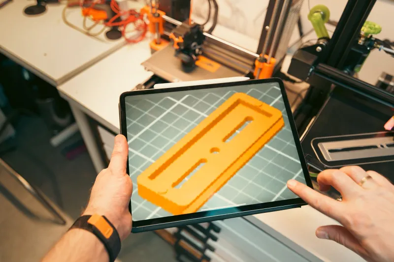
You've been there. The model looks immaculate on screen—every edge clean, every dimension locked in, every surface smooth as glass. You export, slice, and hit print. Then you come back an hour later to find something that looks less like your design and more like a rough draft of it.
This isn't a printer problem. It's not even really a software problem. It's a translation problem—and it starts earlier in the process than most makers realize.
The Illusion of the Perfect Model
CAD software is, by nature, optimistic. It renders curves as true arcs, walls as perfectly uniform solids, and overhangs as if gravity doesn't exist. The printer, on the other hand, operates in the real world—where filament has viscosity, beds have warp, and physics always gets a vote.
The disconnect typically lives in a few predictable places. Wall thickness is a classic culprit. A designer might spec a 0.4mm wall because it looks right in Fusion 360, not realizing that a 0.4mm nozzle physically cannot produce a clean single-pass wall at that spec without artifacts. The slicer tries to compensate, the printer tries to execute, and the result is a mess that looks nothing like the intent.
Then there's the STL export itself. When you convert a native CAD file to STL, you're essentially translating smooth geometry into a mesh of triangles. Set the resolution too low, and curved surfaces come out faceted. Set it too high, and you've got a file so large it chokes your slicer. Most makers default to whatever their software suggests—which is often a mediocre middle ground that introduces subtle geometry errors before the print even starts.
Where the Slicer Makes Its Own Decisions
Here's something that doesn't get said enough: your slicer is making judgment calls you never approved.
When you import a model, the slicer interprets it based on your settings—layer height, line width, infill pattern, support strategy. But it's also making micro-decisions about perimeter ordering, seam placement, and bridging behavior that can dramatically alter the look and structural integrity of your part. And unless you're digging into the preview layer by layer, you won't see those decisions until the print is done.
Kevin Marsh, who runs a small-batch production shop in Columbus, Ohio, learned this the hard way when a batch of enclosure lids started coming out with visible seam lines right across the face of the part. The model was fine. The slicer was placing seams at the point it calculated as geometrically convenient—not where the design called for clean aesthetics. A simple seam alignment setting fixed it, but it took three failed runs and a lot of wasted PETG to get there.
"I thought I had a printer problem for two weeks," Kevin said. "Turned out I had a slicer literacy problem."
Modeling Habits That Print Well
The makers who consistently get first-layer accuracy are the ones who design with the printer in mind from the start—not as an afterthought.
A few habits that make a real difference:
Design to your nozzle, not your screen. If you're running a 0.4mm nozzle, your minimum wall thickness should be at least 0.8mm—two passes. Anything thinner and you're asking the printer to do something it can't do cleanly. Some makers go further and design walls in multiples of their line width so the slicer never has to make awkward partial-pass decisions.
Flat-bottom your overhangs. Overhangs that end in a point or a fine taper are asking for trouble. Wherever possible, design a flat termination point that gives the printer a stable surface to build from. It's a small modeling adjustment that saves a ton of support cleanup.
Fillet your internal corners. Sharp internal corners are stress concentrators in the physical part and geometry headaches for the slicer. A small fillet—even 0.5mm—gives the slicer cleaner toolpaths and gives your part better structural performance. Win-win.
Mind your Z-axis. Vertical dimensions in CAD are exact. In print, they're dependent on your layer height. If your model has a critical feature at 3.2mm and you're printing at 0.3mm layers, you're going to get a 3.3mm result. That might not matter for a decorative piece. It absolutely matters for a functional assembly.
The Export and Import Chain
Once you've got a solid model, how you get it into the slicer matters more than most people think.
For STL exports, bump your chord tolerance down until curved surfaces look smooth in a mesh preview—typically somewhere around 0.01mm to 0.02mm for most parts. If your software supports 3MF export, use it. The 3MF format preserves more geometry data and tends to produce cleaner slicing results, especially for complex organic shapes.
When you import into the slicer, don't assume the model landed correctly. Check orientation. Check that the scale didn't drift (this happens more often than it should, especially when moving between metric and imperial workflows). And run a quick mesh analysis if your slicer supports it—non-manifold geometry, flipped normals, and open surfaces are silent killers that won't show up until mid-print.
Testing Before You Commit
One of the most underused tools in any maker's workflow is the calibration print. Not the generic test cubes you download from a model repository—custom calibration pieces designed to validate the specific features in your actual part.
If your design has a press-fit hole, print a small test piece with just that hole before you commit to a full run. If you've got a thin-wall section, test that wall in isolation. It takes fifteen minutes and a small strip of filament. It saves you from discovering the problem after a three-hour print.
Amanda Torres, a mechanical engineer turned independent maker in Austin, Texas, built a personal library of what she calls "feature validators"—small test prints for threads, snap fits, living hinges, and press fits in every material she runs regularly. "Every time I add a new material or change a nozzle size, I run the validators first," she said. "It's boring, but it means I almost never have a bad full-scale run."
Closing the Loop
The design-to-print gap isn't a flaw in the technology—it's a natural friction point between two different languages. CAD speaks in mathematical ideals. Printers speak in physical constraints. The makers who produce consistent, accurate results are the ones who've learned to be fluent in both.
That means designing with process knowledge, exporting with intention, slicing with scrutiny, and testing before you scale. It's not glamorous work. But it's exactly the kind of disciplined, iterative thinking that separates a maker who gets lucky from one who gets it right—every time.